- 您现在的位置:买卖IC网 > Sheet目录356 > SI8402AB-B-IS (Silicon Laboratories Inc)IC I2C ISOLATOR BIDIR 8-SOIC
Si840x
3.4. Input and Output Characteristics for Non-I 2 C Digital Channels
The Si84xx inputs and outputs for unidirectional channels are standard CMOS drivers/receivers. The nominal
output impedance of an isolator driver channel is approximately 85 ? , ±40%, which is a combination of the value of
the on-chip series termination resistor and channel resistance of the output driver FET. When driving loads where
transmission line effects will be a factor, output pins should be appropriately terminated with controlled impedance
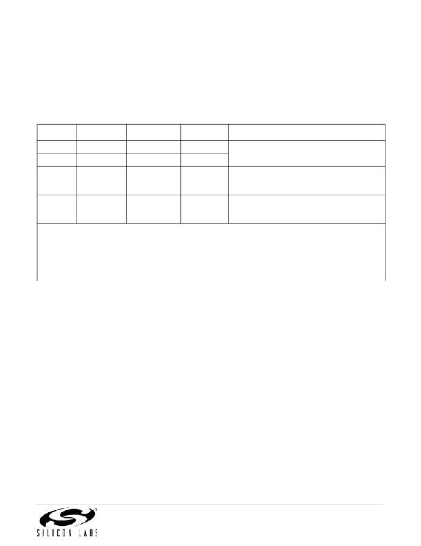
PCB traces. Table 12 details powered and unpowered operation of the Si84xx’s non-I 2 C digital channels.
Table 12. Si84xx Operation Table
V I Input 1,2 VDDI State 1,3,4 VDDO State 1,3,4 V O Output 1,2
Comments
H
L
X 5
P
P
UP
P
P
P
H
L
L 6
Normal operation.
Upon transition of VDDI from unpowered to pow-
ered, V O returns to the same state as V I in less
than 1 μs.
X 5
P
UP
Upon transition of VDDO from unpowered to pow-
Undetermined ered, V O returns to the same state as V I within
1 μs.
Notes:
1. VDDI and VDDO are the input and output power supplies. V I and V O are the respective input and output terminals.
2. X = not applicable; H = Logic High; L = Logic Low.
3. Powered (P) state is defined as 3.0 V < VDD < 5.5 V.
4. Unpowered (UP) state is defined as VDD = 0 V.
5. Note that an I/O can power the die for a given side through an internal diode if its source has adequate current.
6. For I 2 C channels, the outputs for a given side go to Hi-Z when power is lost on the opposite side.
Rev. 1.6
15
发布紧急采购,3分钟左右您将得到回复。
相关PDF资料
SI8405AB-A-IS1
IC ISOLATOR 10M 6CH 2.5K 16SOIC
SI8423BD-B-IS
ISOLATOR 2CH 5KV 150M 16SOIC
SI8435BB-C-IS1
IC ISOLATOR DGTL 3CH 16SOIC
SI8442BB-C-IS1
IC ISOLATOR DGTL 4CH 16SOIC
SI8451BB-A-IS1
IC ISOLATOR DGTL 5CH 16SOIC
SI8460BB-A-IS1
IC ISOLATOR DGTL 6CH 16SOIC
SI8606AC-B-IS1
IC ISOLATOR BIDIR 3.75KV 16SOIC
SI8621ED-B-IS
IC ISOLATOR 2CH 5KV 16-SOIC
相关代理商/技术参数
SI8402AB-B-ISR
制造商:Silicon Laboratories Inc 功能描述:2.5 KV BIDIRECTIONAL I2C ISOLATOR, UNI CLK, 1.7MHZ, SOIC8, L - Tape and Reel 制造商:Silicon Laboratories Inc 功能描述:IC I2C ISOLATOR BIDIR 8-SOIC 制造商:Silicon Laboratories Inc 功能描述:2.5 KV BIDIRECTIONAL I2C ISOLATOR 1.7MHz
SI8402DB
制造商:VISHAY 制造商全称:Vishay Siliconix 功能描述:20-V N-Channel 1.8-V (G-S) MOSFET
SI8402DB_06
制造商:VISHAY 制造商全称:Vishay Siliconix 功能描述:20-V N-Channel 1.8-V (G-S) MOSFET
SI8402DB_08
制造商:VISHAY 制造商全称:Vishay Siliconix 功能描述:20-V N-Channel 1.8-V (G-S) MOSFET
SI8402DB-T1
制造商:VISHAY 制造商全称:Vishay Siliconix 功能描述:20-V N-Channel 1.8-V (G-S) MOSFET
SI8402DB-T1-E1
功能描述:MOSFET 20V 6.8A RoHS:否 制造商:STMicroelectronics 晶体管极性:N-Channel 汲极/源极击穿电压:650 V 闸/源击穿电压:25 V 漏极连续电流:130 A 电阻汲极/源极 RDS(导通):0.014 Ohms 配置:Single 最大工作温度: 安装风格:Through Hole 封装 / 箱体:Max247 封装:Tube
SI8402DB-T1-E3
制造商:Vishay Semiconductors 功能描述:
SI-8402L
制造商:SANKEN 制造商全称:Sanken electric 功能描述:Separate Excitation Switching Type with Coil
